

Article by Juan Jesús García, PhD, Product Manager, Braking Systems in Applus IDIADA
Read Part 1 here and Part 2 here.
This is the third part of the article that presents an in-depth characterization of the judder problem. The objective of the study and the actual case study have been introduced in the first part, whilst the second part focused on some theoretical aspects that need to be understood prior to covering the main test results.
Results
Front suspension vibration response
The analysis of transmissibility measurements based on frequency response functions (FRFs obtained impacting the centre of the wheel knuckles in X, Y, and Z respectively) suggests that the front suspension of Vehicle 1 was stiffer in the X direction. The estimated values of the maximum vibration amplitudes of the vehicle knuckles for unitary excitation and the dominant frequencies of response are listed in table 2.
| Vehicle 1 | Vehicle 2 | |
| X | 35 Hz | 22 Hz |
| Y | 60 Hz | 60 Hz |
| Z | 30 Hz | 30 Hz |
We observe that the front suspension of Vehicle 1 was stiffer in the X direction than the one for Vehicle 2. A higher stiffness in the X direction can induce more high-frequency transmission into the body. However, a reduction in the frequency of the X direction response of the suspension will produce a better coupling of this resonance with the judder phenomenon and also road excitation (< 50 Hz).
Also, a shift of vibration energy in a vehicle body towards low frequency tends to induce less comfort and higher annoyance associated with the vibration effects. This is due to the fact that human sensitivity curves exhibit maximum values between 3 to 30 Hz for vertical vibrations and between 1 and 10 Hz for longitudinal excitations. We also have to consider that steering wheel vibration human sensitivity is higher in the band between 2 to 40 Hz.
Vibration coupling in the response points: seat rail and steering wheel
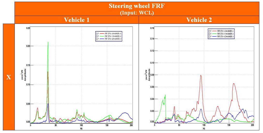
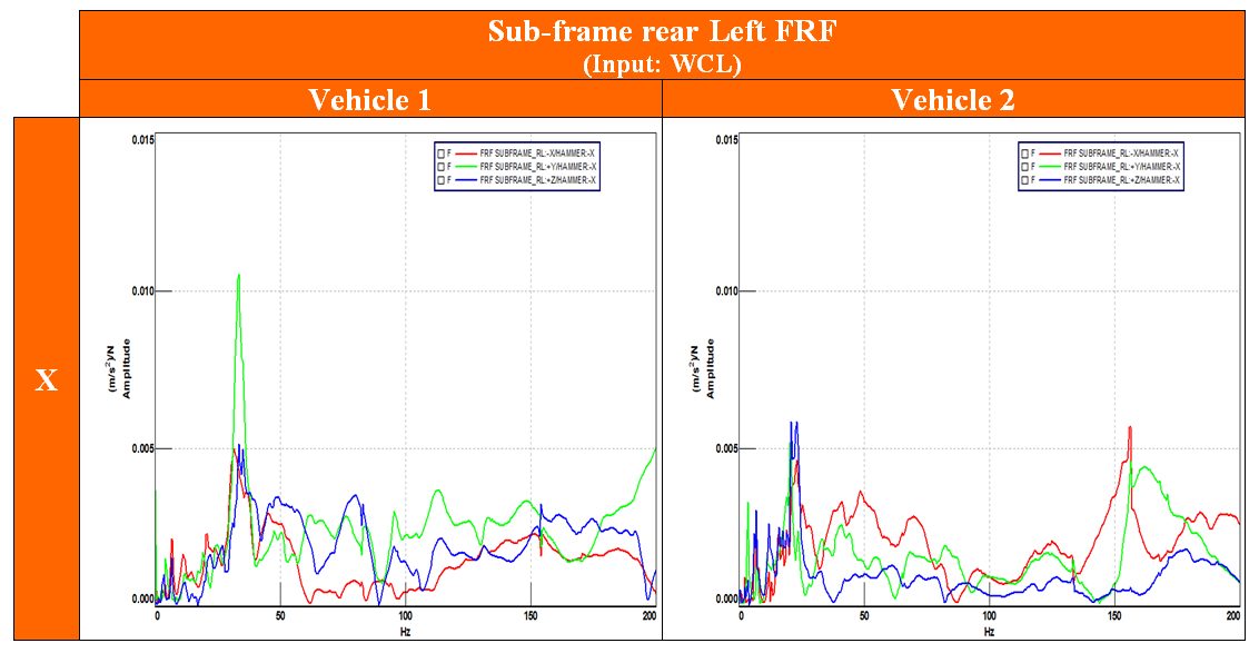
In this section we show the FRF functions measured applying an input force at the knuckle centre point (front suspension) and measuring the responses at the steering wheel and the rear point of the sub-frame of the vehicles. These results are shown in figures 9 to 11. The measured FRFs showed that the impact in Y direction tends to induce high-frequency levels in the above points in Vehicle 2, probably due to a resonance of the sub-frame system or a lack of stiffness in this or other coupled directions.
The steering wheel in Vehicle 2 had a higher sensitivity to input vibration at the wheel knuckle for Y and Z input excitations. This transmissibility to the steering wheel seemed to be boosted by a high input level in the bushing between the LCA and the chassis.
FRF response in vehicles 1 and 2 @ steering wheel position – unitary input force at centre of left wheel knuckle (WCL):


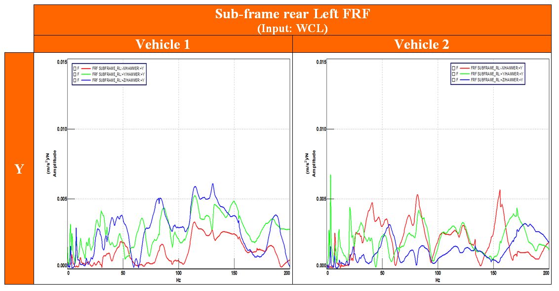
FRF response in vehicles 1 and 2 @ sub-frame rear left position (sub-frame side) – unitary input force at centre of left wheel knuckle (WCL):
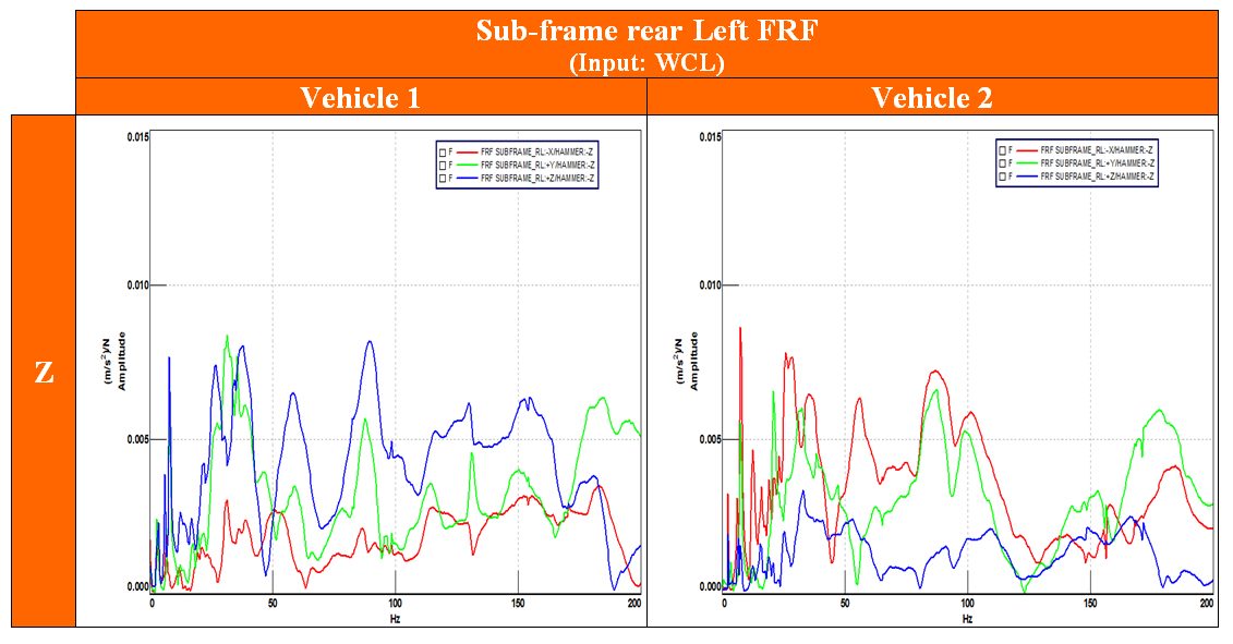
FRF response in vehicles 1 and 2 @ sub-frame rear left position (body side) – unitary input force at centre of left wheel knuckle (WCL):
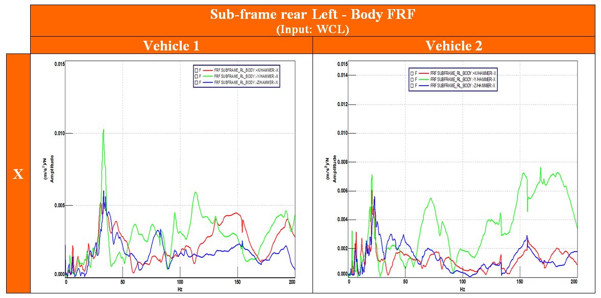
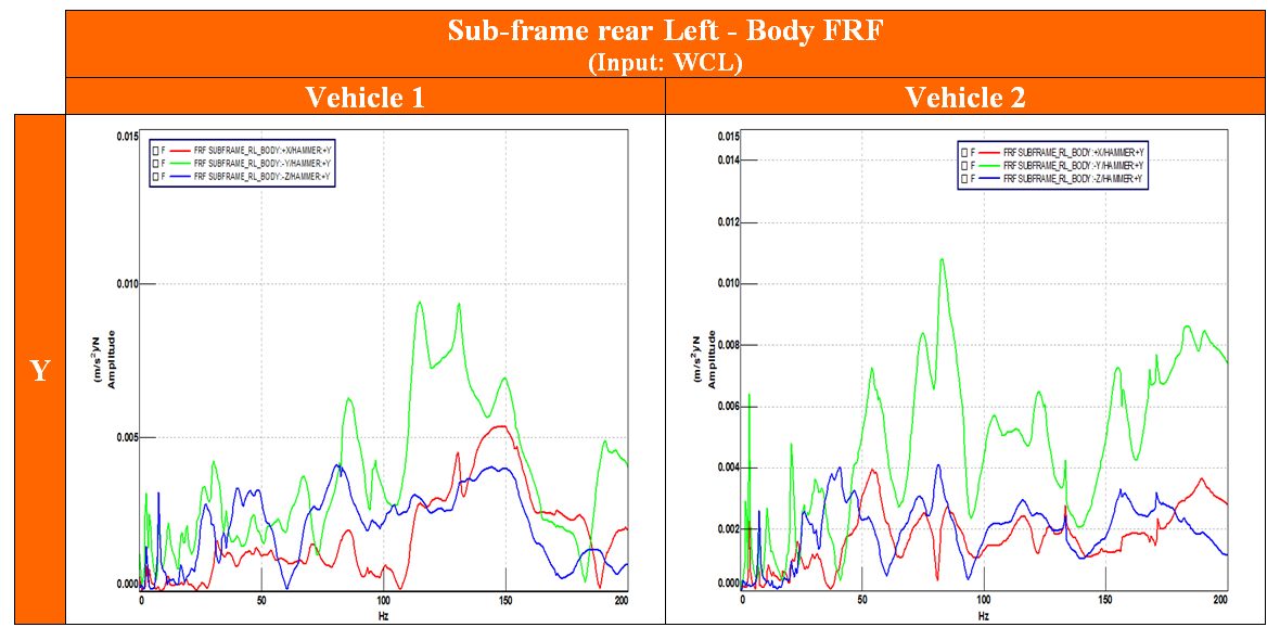
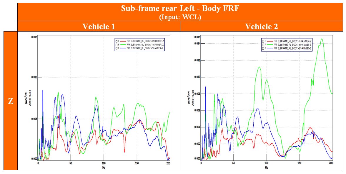
The plots above lead to the conclusion that Vehicle 2 exhibited an increase in the X and Y vibration due to a lower stiffness in the sub-frame reinforcement.
The analysis of the results is to completed in the fourth (and last) part of this article.
About Applus IDIADA
With over 25 years’ experience and 2,450 engineers specializing in vehicle development, Applus IDIADA is a leading engineering company providing design, testing, engineering, and homologation services to the automotive industry worldwide.
Applus IDIADA is located in California and Michigan, with further presence in 25 other countries, mainly in Europe and Asia.


