Sign up for our weekly email to stay on top of the latest news and insights!
Troy, Mich. — This is the third article in a series of four by Narcís Molina, Project Manager, Braking Systems in Applus IDIADA, about the relationship between brake creep groan and brake squeal in disc brakes.
Relationship of Brake Creep Groan and Squeal in Disc Brakes (Part 1 of 4)
Investigation of Relationship between Brake Creep Groan and Squeal in Disc Brakes (Part 2 of 4)
This article investigates how two distinct brake phenomena such as squeal and creep groan can be related to each other during the operational use of a disc brake, as they appear concatenated in time.
The first part introduced the problem and the methodology, while the second part presented the main results associated to creep groan. This third article analyzes the observed displacements under operational groan.
3.1.6. Point Trajectory Analysis
This section develops advanced methods to investigate the detailed movements exhibited by the various parts of the brake during the groan reproduction. The specific aim of this study is to characterize the relative displacements between the pads and the caliper, and to break down the observed total displacements of the pads into two terms: one that is imposed by the caliper (dragged), and another where pads are not held in position by the caliper and, thus, their orientation/position with respect to the disc is not guaranteed by the caliper (uncontrolled).
3.1.6.1. Caliper Housing Deformation
Measurements gathered during the actual creep groan reflect the total movement of the brake assembly. This movement is recorded as acceleration; the associated displacements can be calculated from the double integration of these accelerations. The resulting (total) displacements are those viewed by an inertial system of reference external to the vehicle. Note that these total displacements can be considered as the sum of two components: a rigid body component and a ‘global deformation’ (non-rigid) component, which can be the combination of various factors.
This movement decomposition concept provides an understanding of where the total (measured) vibration displacement is generated, thus becoming paramount to identify the main source of structural deformation or the lack of correct positioning.
The mathematical theory behind the movement decomposition was presented in EuroBrake 2017 and 2019. Applied to this particular brake assembly, as seen in Figure 18 (left), two different coordinate systems are considered in order to estimate what part of the measured vibration of the caliper housing is due to a deformation of the structure itself: e_i is fixed to the anchor, whilst e_i’ to the housing.
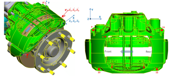
Figure 18: Movement decomposition analysis of the caliper: coordinate systems (left) —e_i is fixed to the caliper anchor; e_i’, to the housing— and reference points (right).
In Figure 19, the study of the non-rigid motion of the caliper housing windows —as defined by the points depicted in Figure 18 (right)— allows the deformation of the housing to be understood.
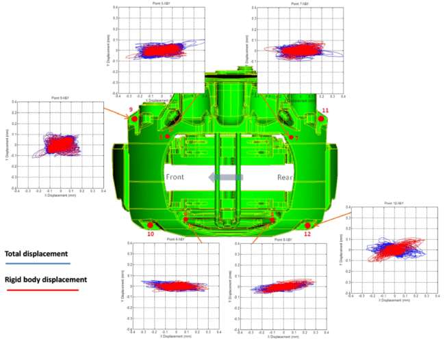
The plots show the vibration behavior of the caliper housing relative to the desired rigid-body performance. The blue curves denote the total measured displacement, while those in red represent the rigid body behavior. Note that all measurements correspond to the unstable creep groan phase and that, the more coinciding are the two displacements, the more rigid is the point.
There is a consistent discrepancy over all the housing points between the total and the rigid-body displacements. Presumably, the movement of the component might be dominated by the mechanical stiffness of the guide pins-bearing assembly.
3.1.6.2. Brake Pads’ Uncontrolled Displacement
A similar approach can be followed for the brake pads, whose total movement can be again broken down as the sum of non-rigid and rigid components —the latest being understood as a dragging displacement, the pads being held in position within the caliper housing (assuming that this part is completely rigid). The non-rigid, uncontrolled movement does not follow the nominal positioning of the pads; presumably is dictated by the combination of various sources of uncertainty, such as:
- Deformation of the caliper.
- Relative movement of the caliper housing with respect to the caliper anchor.
- Mechanical play between the guide pins and the bearings.
- Mechanical play between the pads and the caliper anchor.
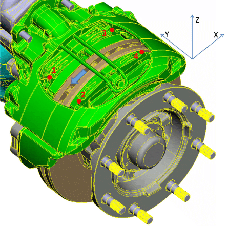
Figure 20: Reference points for the movement decomposition analysis of the pads.
Figure 21 shows the non-rigid movement of the pads, under unstable creep groan, along the xy plane (as defined by the coordinates system; same figure). It is observed that this uncontrolled movement is dominated by the x-direction, i.e. that tangential to the disc. This movement is associated to the stick-slip —and a certain pitch variation, as detailed in Section 3.1.6.3.
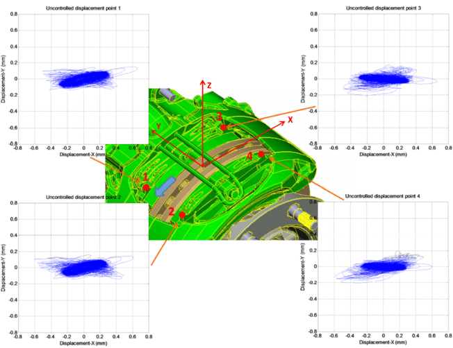
It is understood that the process of creep groan generation, established with the initial stick-slip events, might be boosted by the mentioned uncontrolled movement of the brake pads, thus leading to additional oscillations in the friction interface.
3.1.6.3. Brake Pads’ Pitch Angle
Figure 22 defines the pitch angle (θ_H) of the inner and outer pads with respect to the disc; a positive value of θ_H denotes a clockwise rotation of the pad about the z-axis.
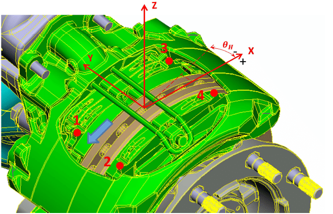
Figure 23 illustrates the experimentally-observed concatenation of pad orientations over the xy plane (‘pitch up’ and ‘pitch down’) and stick-slip, for the inner pad.
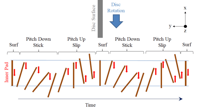
Figure 24 depicts the time history of the pitch angle of both pads —along with a schematic view of their actual position— during the three phases of groan. Results are very sensitive to the groan conditions: a rather transient response is observed during the triggering phase, in comparison with the more steady-state behavior during the charging and unstable phases.
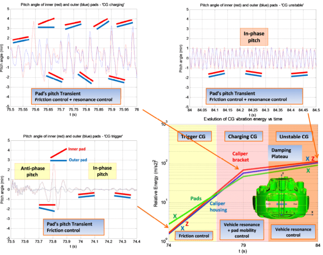
The important conclusion presented here is that the stick-slip occurs simultaneously with pad pitch variation. This means that, in practical terms, the tribological phenomenon is manifested in combination with a dynamic effect that is dominated by the brake design and its dynamic response.
3.1.6.4. Stick-Slip Motion vs Brake Pads’ Orientation
In the brake under investigation, we find that stick-slip is the fundamental triggering effect of creep groan. However, the charging and unstable phases are progressively controlled by the brake-suspension resonances —regardless of the stick-slip condition. This can be inferred by the fact that pad’s vibration and movement during these latter phases is progressively more sinusoidal. Consequently, it is understood that there are two potential approaches to control the creep groan:
- Tribological countermeasures.
- System dynamics countermeasures.
Note that the tribological countermeasures will all have the aim of reducing as much as possible the transients in the time histories of the frictional force when stick-slip occurs —triggering phase in Figure 24. In this case, the transient duration is of the order of about 0.05 seconds, i.e. the excitation frequency band contains energy up to about 20 Hz. If this frequency range contains the fundamental brake and/or suspension resonances, part of the initial stick-slip energy may excite these modes, meaning that the brake will start vibrating with the consequent caliper deformation and pads continuous reorientation —the sum of uncontrolled, tangential displacements and pitch. Indeed, this pitch oscillation can produce an alternative source of brake torque variation that, eventually, may take over the control of the vibration.
3.1.6.5. Mechanical Feedback Loop
In this sub-section, the idea that the initial stick-slip / pads’ pitch phenomena are only a trigger of the tonal response of the truck, being this response controlled by a combination of front axle, structural resonances, is elaborated by means of block diagrams.
- Phase 1: some air pressure (about 2.6 bar) operates the brake chamber, which forces the pads to move against the disc, initiating a steady-state braking operation.
- Phase 2: braking torque variability caused by incipient perturbations in the friction interface, namely stick-slip and/or the reorientation of the pads —due to the uncontrolled tangential displacement or the pitch oscillation (Figure 25).
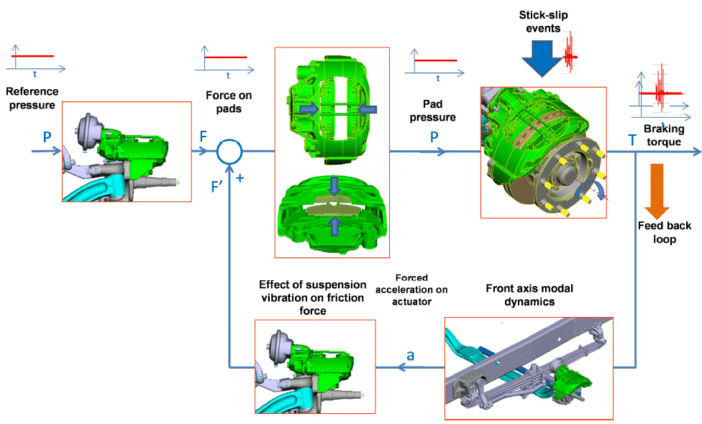
- Phase 3: front axle resonance activation due to the mentioned in-brake perturbations. As seen in Sections 3.1.3 and 3.1.4, the controlling resonance is associated with a synchronized mode involving the axle beam, the steering and the leaf springs.
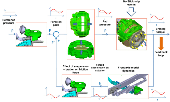
- Phase 4: shaking effect on the brake caliper caused by the vehicle resonance, which generates an alternating position of the pads with respect to the disc —regardless of the initial perturbations found in the friction interface, namely stick-slip or the pitch of the pads. Therefore, the mechanical, positive feedback loop is finally closed.
- Phase 5: non-linear, unstable, self-maintaining tonal response at 63 Hz controlled by the vehicle resonance (Figure 26).
About Applus IDIADA
With more than 25 years’ experience and 2,450 engineers specializing in vehicle development, Applus IDIADA is a leading engineering company providing design, testing, engineering, and homologation services to the automotive industry worldwide.
Sign up for our weekly email to stay on top of the latest news and insights!
Applus IDIADA has locations in California and Michigan, with further presence in 25 other countries, mainly in Europe and Asia.

