Sign up for our weekly email to stay on top of the latest news and insights!
This is the first of a three-part TBR Technical Corner article by Antonio Perez, Emissions and R&D Engineer, Powertrain Department at Applus IDIADA on brake dust emissions during real-world driving.
Introduction
There are many sources of traffic-related emissions, which are usually mainly related to the fuel combustion exhaust. These sources are a high contributor to the emission of particulate matter (PM) to the environment, and nowadays are well characterized and studied, as well as controlled and restricted by current regulations.
However, there are other types of traffic-related emissions which do not come from fuel combustion exhausts: these are known as “non-exhaust” emissions, and include, in order of their contribution from most to least, brakes (brake-related parts, including during off-brake conditions), resuspension, tires, road, abrasion or corrosion of vehicle parts and other sources.
Related post:
Brake Dust: The Inconvenient Truth
These non-exhaust emissions have a large impact on the generation of PM10 and even PM2.5 and are now a topic of great interest in the automotive industry. Brake particle emissions are the largest contributor to these non-exhaust emissions.
Moreover, recent research has demonstrated that brake systems emit ultra-fine particles directly affecting the air quality of cities and human health.
Accordingly, brake dust has become an important topic to study in order to start implementing measurement methodologies that might lead to future test standardization and brake component approval regulations.
In 2014, the European Commission created the Particle Measurement Programme (PMP) Informal Working Group (IWG) to investigate this topic and provide enough data and knowledge to establish future legislation. Hence, the main objective of the PMP is to set up a commonly accepted methodology for measuring brake wear particles. The roadmap of this group has two main activities: task force (TF) 1, now completed and whose aim was to define a standard brake emissions cycle, and TF2 which is in progress and aims to define the measurement equipment, sampling conditions, cooling conditions, etc. for measuring brake dust.
Furthermore, some European Union (EU) funded projects have been working on this issue in order to contribute and complement PMP group activities. Other markets are also involved in this topic, such as Japan and the USA – mainly – and India, Korea and China.
Methodology
IDIADA performed two different testing campaigns in order to fulfil the main targets of the project. The methodology used in these campaigns to measure brake dust emissions on a brake dynamometer is presented in this section. Firstly, the brake integration was done at IDIADA’s test facilities in the U.K. and the emissions measurement systems were set up. Secondly, the testing procedures to be followed and the friction material selected for the tests performed were defined.
Brake integration
In order to develop the brake particle measurement methodology, a brake testing laboratory was conditioned and adapted according to the state-of-the-art methods in this field:
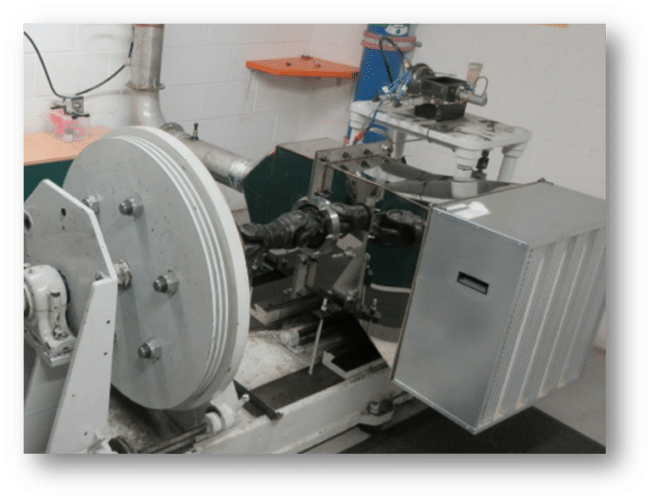
- Sealed House for Emissions Determination (SHED) installation: Figure 1 shows the collection box installation in the brake dyno, isolating the brake system and allowing only clean air to come inside the box through a HEPA filter (class EN1822_H14; highest flowrate of 4000 m³/h). In addition, at the end of the collection box, an extraction system was set up in order to have a defined sampling location.

- Chamber conditioning: the brake dyno selected for the emissions testing was adapted in order to ensure the air coming into the SHED system was clean, avoiding high values of background concentration in the measurements.
- Cycles implementation: the WLTP novel cycle and other cycles created were implemented in the brake dyno control.
- Signals installation: typical brake test analogue signals were installed in the dyno in order to collect additional data useful for the analysis of the results:
- Sliding thermocouples to measure surface brake disc temperature continuously. They were located at the disc effective radius.
- Pressure sensors to measure brake pressure applied in each brake event.
- Analogue sensor for measuring brake dyno speed.
- Air flow measurement both continuous and intermittently.
Particle equipment
Particle Number (PN) and Particulate Matter (PM) measurement systems were used in this project in order to measure brake dust with different technologies:
- On-board system – HORIBA PEMS PN23 nm, for measuring second-by-second PN concentration with a size cut-off of 23 nm.
- PEGASOR Particle Sensor: real-time continuous detector for PN and PM measurements, capable to detect particles up to 3 µm.
- Dekati HR-ELPI+ (High Resolution Electrical Power Pressure Impactor) size distributor and PN measurements. Size range from 6 nm to 10 µm.
- Dekati eFilter for continuous PM measurement (sensitive real-time PM detection). Size upper cut-point is 3 µm.
Test procedures
Two different testing campaigns were performed in the brake dyno. The procedures and protocols followed during those tests were:
- Set-up considerations
- The SHED system was periodically cleaned during the testing campaign.
- The air flow rates defined were 1100 and 600 m³/h.
- The test facility air was not air conditioned.
- There was no cooling control system in the chamber; temperature and humidity were ambient values.
- Particles sampling: A stainless steel 8 mm sample probe was used with 4 x 2 mm orifices. Furthermore, the sample point was located specifically and according to the current exhaust legislation for measuring particle emissions. The diameter of the sample duct was 150 mm.
- Test considerations
- Synchronization was done between emissions measurement equipment and brake dyno currents signals for the post-processing analysis.
- Test start condition: the brake temperature was used for starting the test.
- The background concentration of the capture box was checked at the beginning of the project and at different moments of the testing as well. The results showed a concentration below 100 #/cm³, which is the value used for ensuring the correct background concentration in exhaust emissions testing with an on-board system. It is important to mention that the background checked was done with the PEMS PN23 nm device. This equipment measures solid particles with a size threshold of 23 nm.
- Cycles definition
- WLTP novel cycle: it was defined according to the PMP group cycle definition with some adaptations to these specific campaigns.
- Development cycles: Various cycles were defined to understand particle behavior. the aim was to look at the different parameters that can affect the emissions results, for instance, speed and temperature profile, flow rate, etc.
Friction material
During the testing campaigns of this research project, a segment C vehicle, front left brake corner system was used. The components (pads and disc) used at the beginning of the activities were completely new parts, and the pads friction material was low steel variant. A burnishing process of the pads was followed according to the SAE J2522 (AK Master), section 6.2, before the measurement cycles, in order to achieve the necessary stabilization of the particle emissions and obtain robust and reliable results.
Sign up for our weekly email to stay on top of the latest news and insights!
About Applus IDIADA
With more than 25 years’ experience and 2,450 engineers specializing in vehicle development, Applus IDIADA is a leading engineering company providing design, testing, engineering, and homologation services to the automotive industry worldwide.
Applus IDIADA has locations in California and Michigan, with further presence in 25 other countries, mainly in Europe and Asia.


